|
|
DevelopmentSega Master System / Mark III / Game Gear |
Home - Forums - Games - Scans - Maps - Cheats - Credits |
SMSReader - Components List
Parts for building the SMSReader
Here is a list of electronic components you'll need to build the reader. All of these should be available from any electronics retailer. The catalogue numbers given are for the UK supplier, Maplin Electronics - prices shown are in UK Pounds.
| Component | Qty. | Maplin Code | Maplin Price (ea.) | Total Price |
|---|---|---|---|---|
| Veroboard (Strip Board), 39 copper strips x 62 holes per strip | 1 | JP50E | 1.95 | 1.95 |
| 16V 22uF Tantalum Capacitor | 1 | WW72P | 0.42 | 0.42 |
| 35V 470uF Electrolytic Capacitor | 1 | VH47B | 0.37 | 0.37 |
| 16V 100nF Ceramic Capacitor | 3 | YR75S | 0.12 | 0.36 |
| 100V 220nF Ceramic Capacitor | 1 | RA50E | 0.09 | 0.09 |
| SIL Resistor 47k ohm | 1 | RA31J | 0.14 | 0.14 |
| 1N4001 Rectifier Diode | 1 | QL73Q | 0.04 | 0.04 |
| 7805 +5 volt regulator | 1 | QL31J | 0.67 | 0.67 |
| 4040 CMOS 12 bit binary counter IC | 2 | QW27E | 0.84 | 1.68 |
| 74HC00 Quad CMOS NAND gate IC | 1 | UB00A | 0.42 | 0.42 |
| 16 pin DIL IC socket (for the 4040s) | 2 | BL19V | 0.16 | 0.32 |
| 14 pin DIL IC socket (for the 74HC00) | 1 | BL18U | 0.16 | 0.16 |
| 50 way 0.1in pitch edge connector | 1 | JC01B | 0.94 | 0.94 |
| 2.1mm power connector | 1 | RK37S | 0.42 | 0.42 |
| 25 Pin D-type right angled plug connector | 1 | FG68Y | 0.98 | 0.98 |
| 2.2k ohm metal film resistor | 2 | M2K2 | 0.06 | 0.12 |
| 100V 4.7nF Ceramic Capacitor | 2 | WX76H | 0.07 | 0.14 |
| Total (excluding VAT) | 9.22 | |||
| Total (including VAT) | 10.83 | |||
As you can see, it's possible to build the SMSReader for very little money. If you already have some of these parts or can obtain them from scrap, you can reduce the cost even further.
If you're unable to obtain the necessary parts where you live, I can sell you a complete kit of parts for building a SMSReader, or for modifying a cartridge to make a rewritable cart. Contact me at the address linked above.
You will also need some insulated wire, by the way, to make the necessary board connections. Solid core bell wire is very cheap - get several different colours if you can, to aid identification. Stranded wire is not as suitable, since it's easy for individual strands to come loose and cause a short circuit.
Wire wrapping wire, on the other hand, is very thin solid core wire. Because of its small diameter, it breaks easily, but on the other hand is manoeuvrable and very easy to work with. It's not so good for Veroboard wire-up, but a good choice if you're going to modify cartridges as described in a later section.
Other parts you'll need
There are a couple more items you're going to need to use the SMSReader...
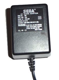
Power supply unit (AC adaptor)
The SMSReader is designed to be powered from an unregulated DC supply of between 9 and 12 volts, and negative polarity. The PSU supplied with the Sega Master System (I or II) itself is more than good enough for the job; or you could just use a cheap "universal" plug-pack adaptor such as those available from market stalls, etc. There is no point in splashing out on an expensive adaptor.
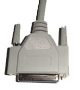
Parallel cable
A standard 25-pin male-to-female parallel cable is needed (not the Centronics type used for a printer). They may be sold as "parallel extension" or "printer extension" cables.
The type of parallel cable you use is fairly important, and will have a bearing on how reliably cartridges can be read or written. For best results, the lead should use good quality shielded cable, and be kept fairly short (2 metres or less). You may be able to get away with using a cable longer than this, but in general, the shorter the better.
Description of components
Veroboard
(39 tracks by 40 holes)
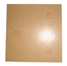
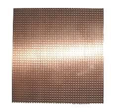
Veroboard (or "strip board" to use the generic name - Veroboard is a registered trade mark) is SRBP board with a matrix of holes 0.1 inch apart. One side of the board (the underside) is coated with conductive copper tracks, allowing components to be soldered into the board. It's a cheap and easy way of constructing electronic circuits.
A piece of Veroboard 39 tracks wide with 40 holes per track is required for this project. If you have a larger piece, it can be scored with a knife and broken to the correct size. The board is shown above: the left picture shows the top (or component) side of the board; while the right picture shows the underside, with its copper tracks running top to bottom.
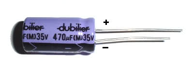
Electrolytic Capacitor
(470uF, 35 volts)
The DC output of a typical AC mains adaptor is not constant, but carries variations known as ripple voltage. We add this capacitor between supply input and Ground to "smooth out" the variations and produce a constant DC supply, hence the term "smoothing capacitor".
''(Note that we use the term Ground in this case to describe the negative side of the DC supply, as opposed to the positive side.)''
An analogy can be drawn with the hot-water tank or cistern in your home. When such a tank is fitted, the output (i.e. the water flowing out of your tap, shower, etc.) is not affected by variations in the mains water supply pressure.
Electrolytic capacitors have a can-like appearance as shown above. They are polarised, which means they have a positive and a negative terminal. You MUST connect the capacitor the right way round - failure to do so could cause the capacitor to explode! The negative terminal is marked with a series of minus signs (-) down the side of the capacitor with arrows pointing to it - see the picture.
The capacitor above is a radial type, with both terminals at one end. This is the most convenient type to use for mounting on a circuit board or Veroboard. Axial electrolytics also exist - they have the positive terminal at one end, and the negative one at the other.
The capacitor should have a rated voltage of at least twice the DC input. Given that our SMS AC adapter has a rated output of 9 volts, which could be up to 12 volts in practice, a capacitor rated for at least 25 volts is recommended, preferably 35 volts to be on the safe side.
The amount of charge per volt that a capacitor stores is measured in Farads (F). The Farad is a very large unit (1 Farad capacitors are the size of beer cans!) so we use subdivisions such as uF (microfarad), nF (nanofarad), pF (picofarad). These are equivalent to 1 millionth (1x10⁻⁶), 1 thousand millionth (1x10⁻⁹), and 1 million millionth (1x10-12) of a Farad respectively.
A suitable value for smoothing in this case is 470uF, but using a slightly larger value such as 1000uF is perfectly acceptable. There is always some leeway in the use of electrolytic capacitors, since they are typically low tolerance (i.e. their values are prone to variation) in any case.
Electrolytic capacitors are one of the few types of electronic component which have a "shelf life". As they age, they dry out and become less effective (over the course of about 10 to 20 years). For this reason, you should always buy new electrolytic capacitors, rather than using ones from scrapped equipment. This is especially important for large power supply capacitors, which are typically worked very hard and run very hot.

Rectifier Diode
(1N4001)
A diode is a component which allows a current to flow in one direction only. We use one here to protect the SMSReader from damage in case we accidentally reverse the polarity on the AC adapter.
A rectifier diode of the 1N400x series should be used; the 1N4001 is as good as any for this purpose. The positive terminal of the diode is marked by a white or silver band around the component body - see the photograph above.

Voltage Regulator
(7805 +5v regulator, 1 Amp rated output)
In a project of this nature, we need a stable, constant 5 volt DC supply. It's the job of a voltage regulator IC to take the variable, unregulated DC input and turn it into a constant supply we can use.
Two common families of fixed voltage regulator exist - the 78xx series for positive voltages, and the 79xx series for negative voltages. The rest of the part number consists of the output voltage, i.e. 7805 for +5 volts, 7812 for +12 volts, 7905 for -5 volts.
Regulators rated for different currents are available, such as 7xLxx series (e.g. 79L05) for 0.1 Amps and 7xSxx series (e.g. 78S12) for 2 Amps. The standard 7805 (no letter in the middle) is rated at 1 Amp and is perfectly acceptable to use in the SMSReader.
The regulator package is designed to take a heatsink, but the 7805 in the SMSReader doesn't get hot enough to justify fitting one.
If you're looking for scrap components, just about any piece of consumer electronic equipment will yield regulators of various kinds.
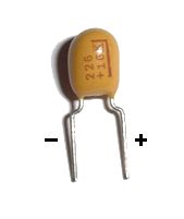
Tantalum Capacitor
(22uF, 16 volts)
A tantalum capacitor is a small, highly tolerant electrolytic capacitor in a bead-like package. Like the standard "aluminium can" electrolytic, it is polarised. The positive terminal is marked with a stripe and/or a plus sign on the body of the capacitor.
Note the shorthand markings used on the capacitor body. "226" means "22 times 10 to the power 6 picofarads", 22000000 pF, i.e. 22uF. Ceramic capacitors are marked in a similar way.
In the SMSReader, this tantalum capacitor is fitted at the output of the voltage regulator for decoupling purposes. See the section on ceramic capacitors for an explanation of this.
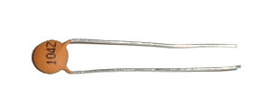
Ceramic Capacitors
(3 x 100nF 16v, 1 x 220nF 100v)
Ceramic capacitors are small, non-polarised capacitors with low values of capacitance. They are used here for decoupling, which I'll try to explain as follows.
During operation, digital ICs (such as the 74HC00 and two 4040s used in the SMSReader) will not draw a constant current from the power supply. Rather, the on-off nature of digital operation will produce quick, relatively large changes in the amount of current drawn. This has the side effect of producing large, momentary voltage increases ("spikes") on the Ground lines, which are liable to affect the operation of other ICs. This is known as "earth bounce".
We use capacitors connected between +5 volts and Ground to remove these spikes - this is known as decoupling. For best results a capacitor of around 100nF is placed between +5 volt (Vcc) and Ground (Vss) pins of each digital IC (three in this case), and a tantalum capacitor of around 22-47uF is placed close to where the power lines enter the circuit (i.e. at the output of the 7805 regulator).
Finally we connect a 220nF capacitor between ground and input of the 7805 regulator, as close to the regulator pins as possible. The arrangement described here should keep the supply clean and constant, to ensure reliable operation of the ICs.
Capacitor markings are the same as for tantalum capacitors - the first two digits are the value and the third is the number of zeroes. So "104" is a 100000 picofarad or 100nF capacitor, and "224" is a 220000 pF or 220nF capacitor. The letter following the three numbers indicates tolerance, but that's not really important for this application.
The 100nF capacitors should be rated for 16 volts or more, and the 220nF should be rated for 35 volts or more.
Two more ceramic capacitors, 4.7nF ones, are used for filtering purposes on the Reset and Clock lines - see the Troubleshooting section and read the solution to problem 1. The idea is to improve reliability by filtering out transient pulses which might trigger a spurious clock or reset. This is particularly important if you use 74HC4040s rather than regular 4040s; the 74HC chips have something of a "hair trigger" and the slightest spike can affect them.
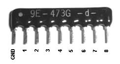
Resistors
(8 way 47kohm with common pin)
A SIL (single in-line) resistor, pictured above, contains several resistors of the same value in a single package. The resistors are "commoned", that is, one lead out of every resistor is wired with all the others into a single (common) pin, shown as GND in the photograph. The common pin (usually the leftmost pin) is marked with a spot on the case. Markings are similar to ceramic capacitors: "473" indicates 47000 ohms or 47 kohms.
We use the SIL resistor for pull-down on the data lines (8 data lines, hence 8 resistors). This is to cure a problem with some designs of parallel port: they require that we "pull down" the data lines to Ground (logic zero). In the vast majority of cases the SIL resistor isn't necessary, but there's no harm in fitting it anyway.
We also use a couple of ordinary 2.2 kohm resistors (not pictured) for pull-up on the Reset and Clock lines. The purpose of this is explained in the Troubleshooting section. Ordinary resistors are too small to have the value printed on them, so their resistance is indicated by coloured bands on the casing. 2.2 kohm is represented by red, red, black, brown bands; or alternatively three red bands.
Digital ICs
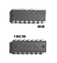
(2x 4040 CMOS 12-bit counters, 1x 74HC00 quad NAND gate, both DIL packages)
We use two 4040 counter chips to address locations in the cartridge ROM. One chip is used for the low byte of the address, the other for the high byte - so only eight outputs of the 12 available are used. There are 16 pins on the 4040 - Vcc (+5 volts), Vss (Ground), 12 output pins, and Reset and Clock pins.
You can use 74HC4040 chips instead of 4040s if you wish, though the 74HC parts are a lot more susceptible to noise on the Clock and Reset lines. See the Troubleshooting section, problem 1, for steps towards solving noise-related problems.
The 74HC00 is used to implement the logic seen in the lower part of the schematic (see the Overview section). It's a logic IC containing four NAND gates in a single package.
Choose the DIL type of chip package (with 0.1 inch leg spacing), rather than a surface mount type.
Both these chip types use CMOS technology and are therefore extremely vulnerable to static electricity. They are supplied in anti-static packaging, and to minimise the potential for damage we use sockets rather than soldering them to the board directly.
IC Sockets
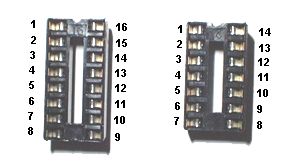
(1x 14 way DIL, 2x 16 way DIL)
These are simply sockets that we solder to the board and plug our chips into, rather than risk damage by soldering chips directly to the board. They are also more convenient in that if a chip is faulty, we can replace it easily without having to mess about desoldering it.
The photograph shows how the IC pins are numbered - down the left hand side, and up the right. There is a notch at the top for orientation, corresponding to the notch on the IC itself.

Edge Connector
(50 way 0.1 inch pitch, PCB mounting)
The edge connector is the socket which connects the SMSReader to the SMS cartridge itself. Fortunately Sega used a fairly standard connector type for the US and European Master System - you should be able to get one quite easily, without having to hack apart your SMS.
You want a straight (i.e. not right angled) connector, with two rows of 25 pins. The pins should be 0.1 in. apart.
Game Gear cartridges, Sega Cards, and SG1000/SC3000/Japanese Mark III cartridges use different types of connectors. You'll need to make adaptors if you want to use these with your SMSReader.
D Connector
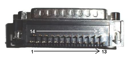
(25 way, right angle, male PCB mounting connector)
This is to connect the SMSReader to the parallel port. The pins don't fit the holes of the Veroboard, so the connector is glued to the board instead and wires soldered to the pins.

Power Connector
(barrel type, 2.1mm, PCB mounting socket)
This is the connector that the AC adapter plugs into; again, glued onto the Veroboard since the pins don't fit the holes.
The connector is wired in negative configuration, with the positive connection on the outside - this allows a SMS or Mega Drive AC adapter to be used.
< Tools you'll need | SMSReader | How to solder >

